Enterprise Networking - Cisco Packet Tracer
Enterprise Networking - Cisco Packet Tracer
INTRODUCTION
Already having experience with real servers, firewalls and other machines. I decided it’s time to give simulation a try.
So this blog will showcase the Enterprise Networks I have designed using Cisco Packet Tracer.
Personally I would have liked to make a walk-through of all these network designs, but as these were too time consuming, I decided not to. So I had included the project task and results only… for now.
The project file of all these networks are available on my github.
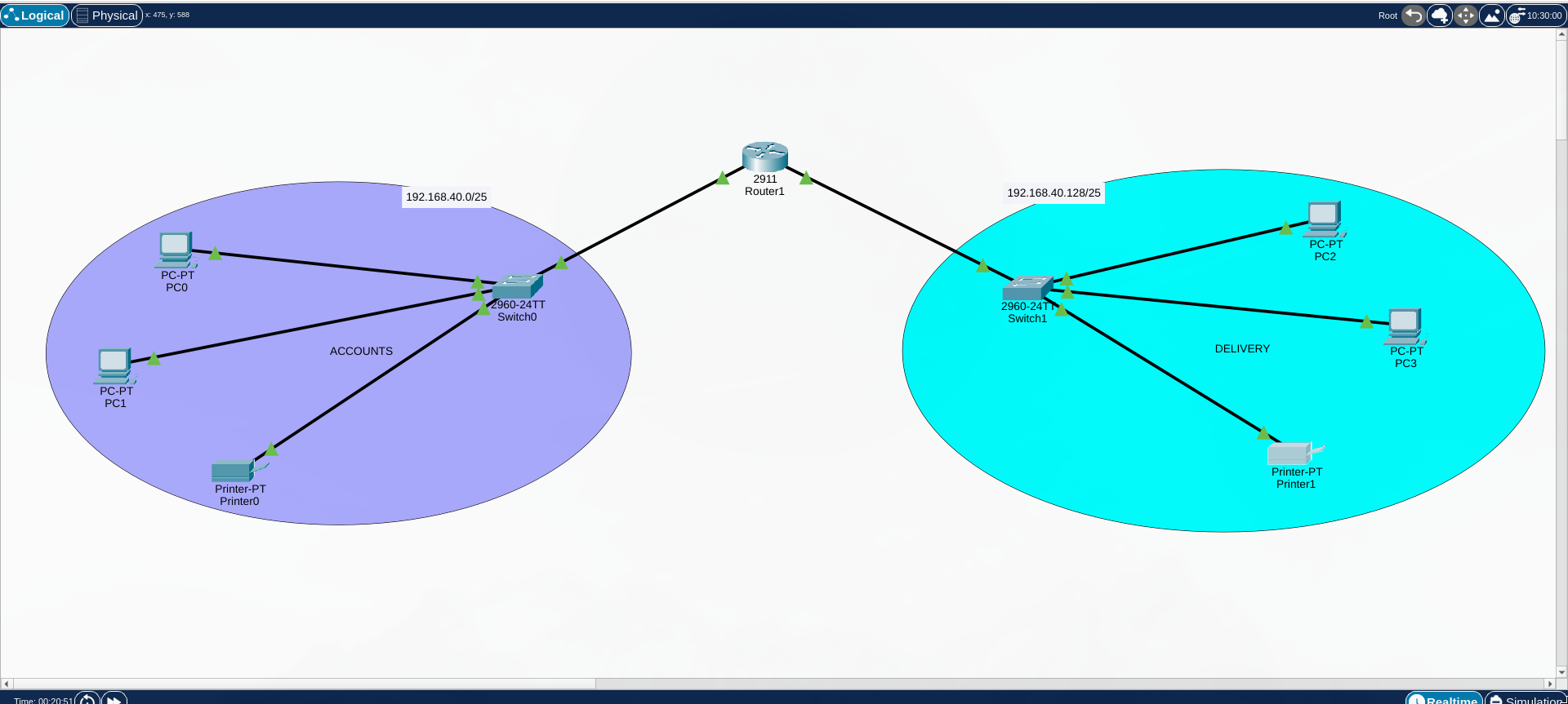
NETWORK 1
The most basic network
TASK:
- Each department should contain at least two PCs.
- Appropriate number of switches and routers should be used in the network.
- Using the given network 192.168.40.0, all interfaces sould be configured with correct IP addresses, subnet mask and gateways.
- All devices in the network should be connected using appropriate cables.
- Test communication between devices in both ACCOUNTS and DELIVERY departments.
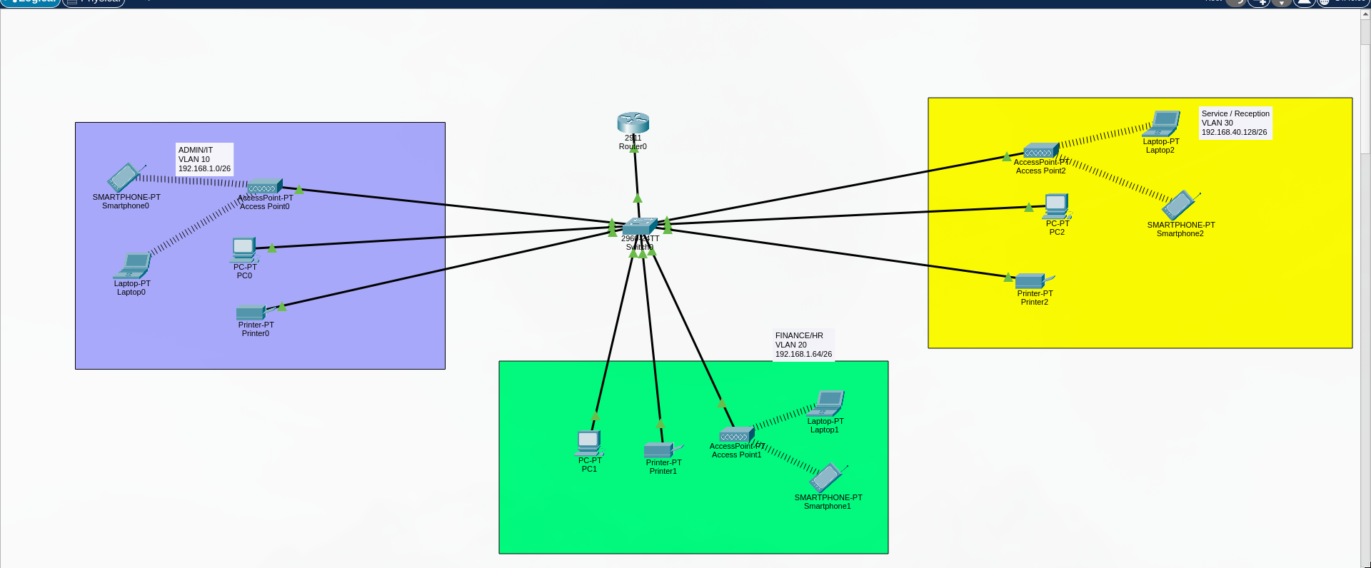
NETWORK 2 - SMALL OFFICE HOME OFFICE (SOHO)
TASK:
- One router and one switch to be used (all CISCO products).
- 3 departments (Admin/IT, Finance/HR and Customer service/Reception).
- Each department is required to be in different VIANS.
- Each department is required to have a wireless network for the users.
- Host devices in the network are required to obtain IPv4 address automatically.
- Devices in all the departments are required to communicate with each other.
Assume the ISP gave out a base network of 192.168.1.0, you as the young network engineer who has been hired, design and implement a network considering the above requirements.
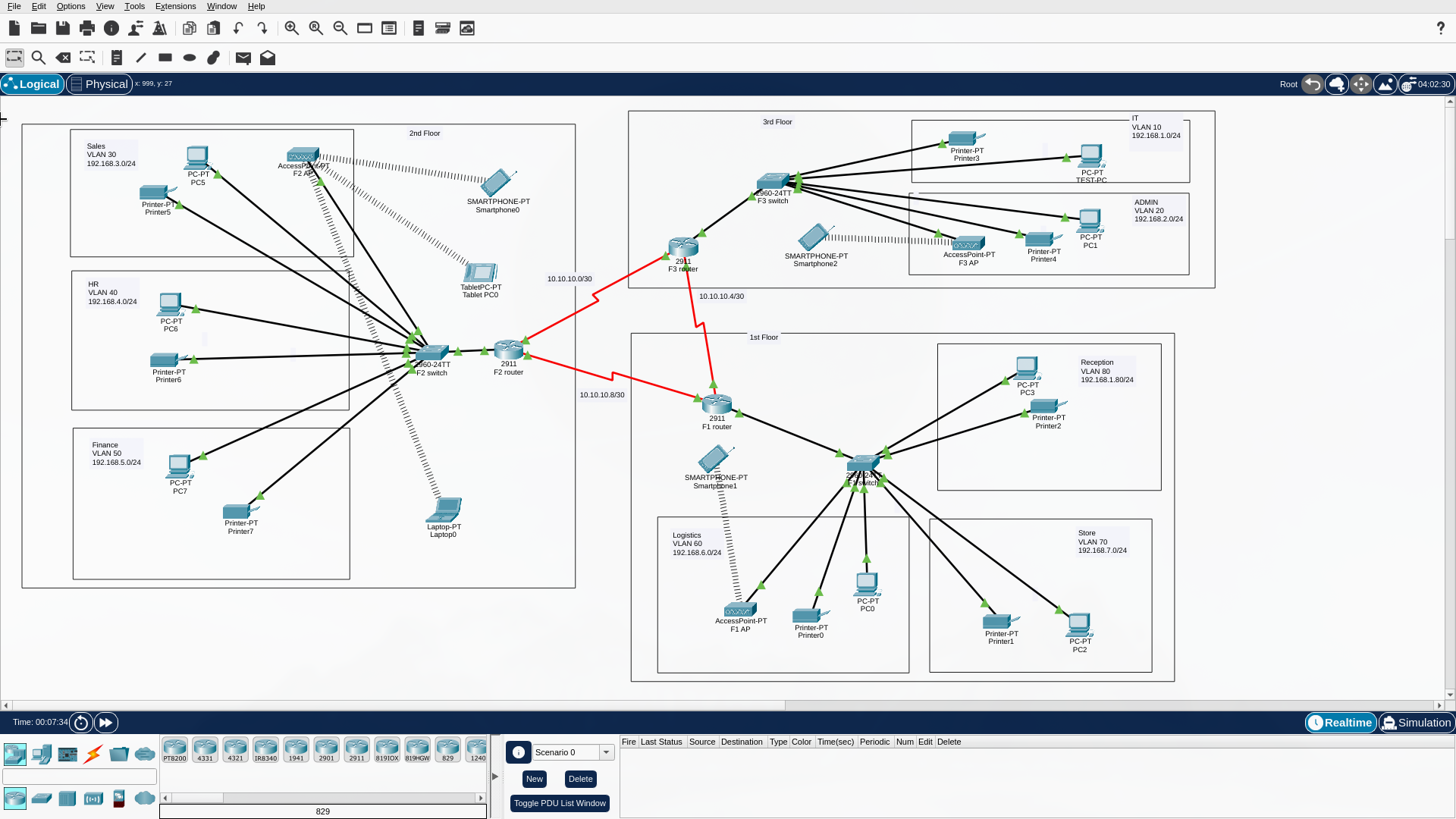
NETWORK 3 - HOTEL NETWORK
TASK:
- There should be three routers connecting each floor (all placed in the server room in IT department).
- All routers should be connected to each other using serial DCE cable.
- The network between the routers should be 10.10.10.0/30,10.10.10.4/30 and 10.10.10.8/30.
- Each floor is expected to have one switch (placed in the respective floor).
- Each floor is expected to have WIFI networks connected to laptops and phones.
- Each department is expected to have a printer.
- Each department is expected to be in different VLAN with the following details;
1st Floor;- Reception- VLAN 80, Network of 192.168.8.0/24
- Store- VLAN 70, Network of 192.168.7.0/24
- Logistics- VLAN 60, Network of 192.168.6.0/24
2nd Floor; - Finance- VLAN 50, Network of 192.168.5.0/24
- HR- VLAN 40, Network of 192.168.4.0/24
- Sales- VLAN 30, Network of 192.168.3.0/24
3rd Floor; - Admin- VLAN 20, Network of 192.168.2.0/24
- IT- VLAN 10, Network of 192.168.1.0/24
- Use OSPF as the routing protocol to advertise routes.
- All devices in the network are expected to obtain IP address dynamically with their respective router configured as the DHCP server.
- All the devices in the network are expected to communicate with each other.
- Configure SSH in all the routers for remote login.
- In IT department, add PC called Test-PC to port fa0/1 and use it to test remote login.
- Configure port security to IT-dept switch to allow only Test-PC to access port fa0/1 (use sticky method to obtain mac-address with violation mode of shutdown.)
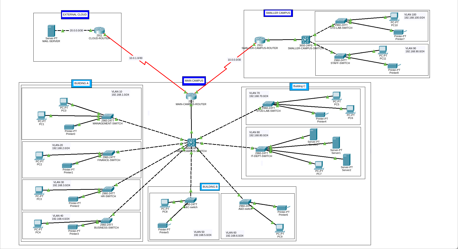
NETWORK 4 - CAMPUS NETWORK
- University location. Main Campus
- Building A: Administrative staff in the departments of management, HR and finance. The admin staff PCs are distributed in the building offices and it is expected that they will share some networking equipment (Hint: use of VLANs is expected here). The Faculty of Business is also situated in this building
- Building B: Faculty of Engineering and Computing and Faculty of Art and Design.
- Building C: Students’ labs and IT department. The IT department hosts the University Web server and other servers
- There is also an email server hosted externally on the cloud.
Smaller campus: Faculty of Health and Sciences (staff and students’ labs are situated on separate floors)
- Each department/faculty is expected to be on its own separate IP network.
- The switches should be configured with appropriate VLANs and security settings.
- RIPv2 will be used to provide routing for the routers in the internal network and static routing for the external server.
- The devices in building A will be expected to acquire dynamic IP addresses from a router-based DHCP server.
This post is licensed under CC BY 4.0 by the author.